While designing my Amateur Radio V/U satellite communications station using omnidirectional antennas, I toyed with the idea of relay-based TX/RX switches with integrated 3dB power dividers to supply signals to a monitoring SDR without the filters of the IC-9700 in the receive chain. This thought was an alternative to using the PTRX-9700 Pandapter as a signal cloning device, and it had the added benefit of being able to use more of the M2 Antennas Eggbeaters’ frequency ranges (the full 136-148 MHz and 400-470 MHz advertised). Unfortunately, this system configuration resulted in insufficient SNR for decoding much telemetry or other signals in the 146/433 MHz Amateur Radio V/U Satcom Bands wihtout adding a mast-mounted pre-amp. Despite this, my quest to explore this technical solution in a world filled with covid-driven part scarcity led to a useful development regarding a common MFJ product.
I fell into the same trap as K1GMM and purchased some MFJ-1708B RF Sense TR Switches thinking they were identical in function to the MFJ-1708B RF Sense SDR Receiver TR Switches. The Switches I bought used a common circuit board design with the SDR model switches, but the non-SDR model did not split the RF receive output; rather, it only served it to the “REC” output. MFJ, like Ten-Tec, provides schematics for many of their products, so I set out to see if I might easily convert this non-SDR model switch to perform as the SDR one.
While the physical circuit boards used for the various models of MFJ-1708B devices are all the same, the populated portions of the layout differ in 4 ways:
- R1 is NOT present on SDR Version
- JP3 is disconnected/NOT present on SDR Version
- SMD Center-Tap Transformer TR1 for the -3dB RF Splitter is present on SDR Version
- A 100 Ohm Resistor shorts the end-point leads of TR1 on SDR Version
The differences are shown in red markup below:
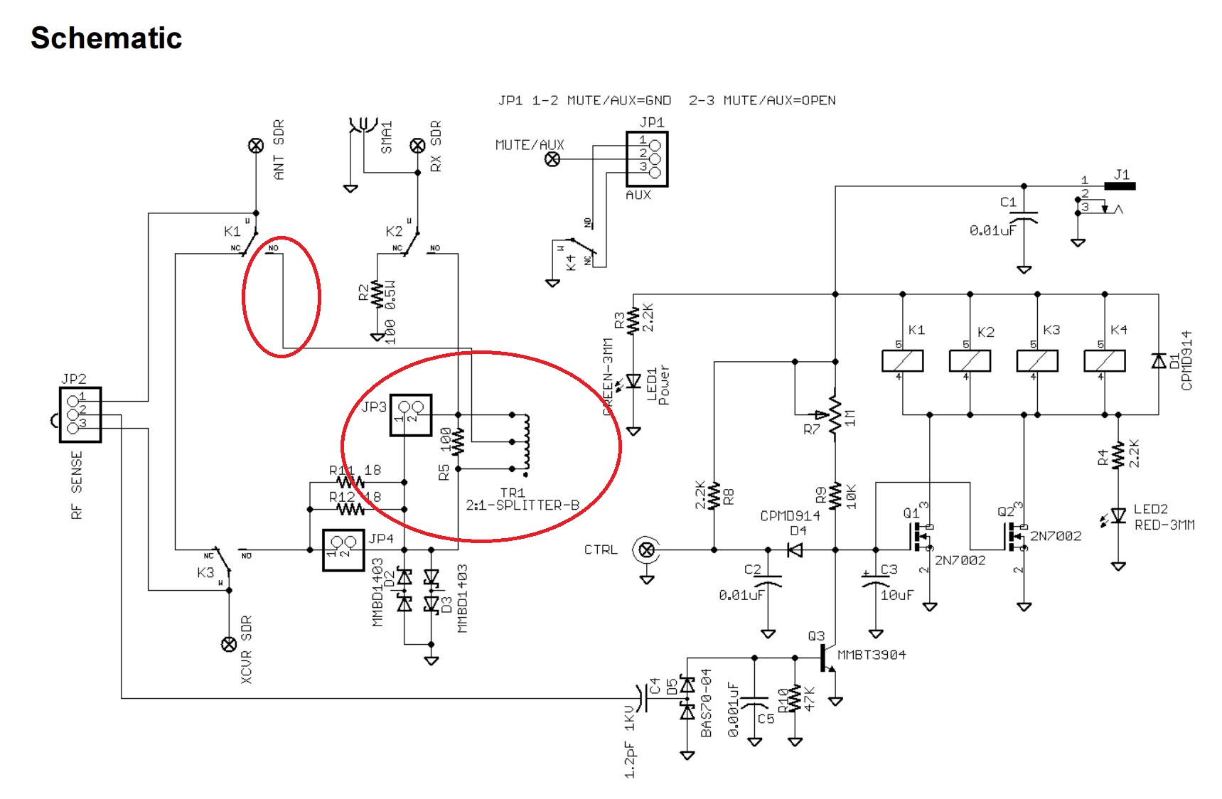
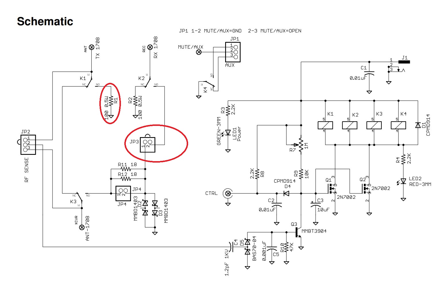
The raw schematics come from the manuals available directly from MFJ:
All of the components required to convert the non-SDR version to the SDR version are likely to be found lying around a typical hobbyist electronics lab except the power splitter transformer, although it’s not hard to find something workable for < $5 a piece on DigiKey, Mouser, etc. I measured by hand using a caliper the footprint for the power splitter on the board and sourced a MAPD-011039 2-Way Power Divider capable of covering 1.218MHz to 5 GHz with an insertion loss of 1.2 dB in a 0.163" L x 0.167" W x 0.142" H (4.15mm x 4.25mm x 3.60mm) 6-SMD, No Lead package for $3.58/pc. (MAPD-011039)
Performing the 4 changes shown in the schematics above yields a functional converted RF switch.